Optical Projection Tomography
Principle
Optical Projection Tomography (OPT) is a 3D microscopy technique invented by J. Sharpe and first proposed in a paper in 2002. OPT can measure both morphological structure of a specimen and its functional imaging in 3D. OPT fills a critical gap in biomedical 3D imaging: it has much higher resolution than Magnetic Resonance Imaging (MRI) and, at the same time, covers a wider field of view than confocal microscopes.
In brief, OPT is very well suited for samples with size in the millimetre scale, that can be “cleared” so that light can pass through them. For a cleared sample OPT works in much in the same way as computed tomography (CT) does with x-rays. A number of images (projections) are collected as the sample rotates about an axis. The 3D volume data is then reconstructed from the projections using mathematical algorithms.
If you would like to learn more about our expertise in micro-CT and related image analysis take a look at our post on automated segmentation using k-means clustering, and our post on quantitative porosity analysis of volumetric data.
The sample image can be formed using either light absorption (attenuation tomography) or the fluorescence signal from the sample (emission tomography), depending on the kind of illumination used. The two types of scans can be acquired during the same sessions and the images are automatically co-registered.
Our OPT system
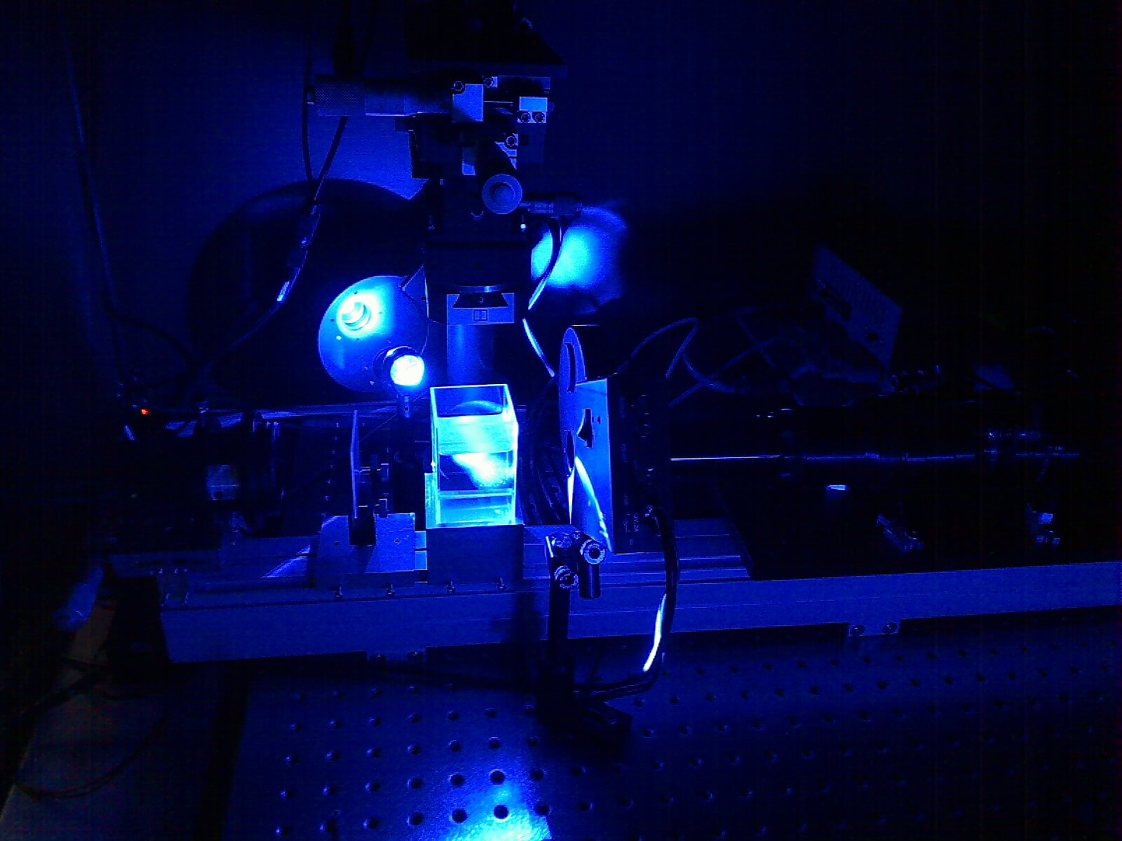
We recently developed and installed an OPT system at Monash Micro Imaging (Monash University) as a result of a combined effort of Instruments and Data Tools, Dr. Kieran Short, Dr Robert Bryson-Richardson and A/Prof Ian Smyth. The system was designed to be shared amongst users of the facility. For this reason we designed it to have an optimal balance between advanced functionalities and user-friendliness.
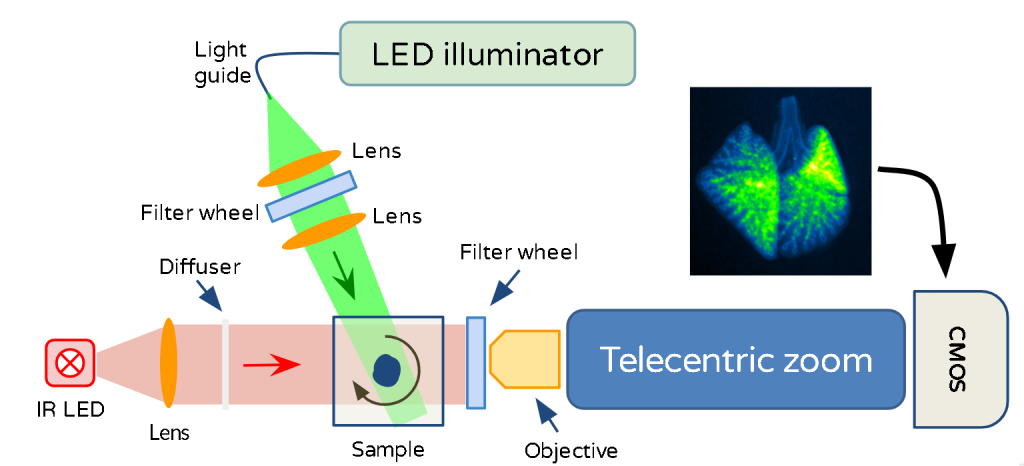
The morphological sample structure is measured in transmission mode using an infrared (IR) LED illuminator. The shadow of the sample, illuminated by infrared light, is measured as the sample rotates. 3D functional imaging is made using fluorescence mode using a multiple LED illuminator. LED light is used to excite fluorophores loaded in the specimen. The specific LED and the filters are chosen depending on which fluorophores are to be measured. Fluorescence projections are measured while the sample rotates. Reconstruction algorithms are then used to derive the 3D distribution of the fluorophores.
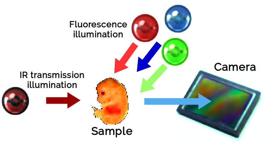
Cartoon of the measurement principle of Optical Projection Tomography
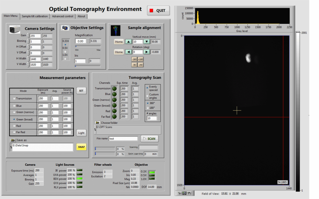
The instrument is operated with a custom build control system written using NI LabView™. This is how the control system GUI looks like.
Results
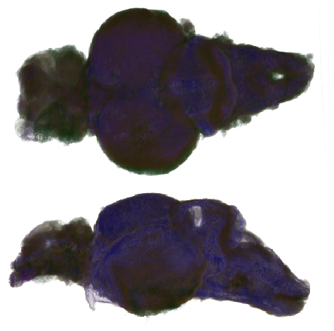
3D rendering of a zebrafish brain imaged by Optical Projection Tomography
The reconstructed volume of the sample can also be rendered in 3D. As an example, the 3D rendering of a zebrafish brain is shown on the left. Sample courtesy of Benjamin Lindsey (Jan Kaslin’s Group at ARMI, Monash University). Data taken by Kieran Short (School of Biomedical Sciences, Monash University).